Chemical technologies for gas and oil wells · Uzbekistan

Production optimization on problem wells

We bring back on the wells that accumulate liquid and go idle, and hold them at stabilized flowing conditions — with no blowdowns, no pumps and no permanent presence at the wellhead.

Manufactured in Texas, USA · supply and implementation · A single engineering point of contact
What lies behind it

A broad range of formulations

70+ grades covering the full range of problems: fluid, salinity, bottomhole temperature and well operating regime.

Continuous monitoring

High-frequency wellhead pressure logging 24/7: operating regimes, downtime, blowdowns,

Algorithms and AI

Automated data processing: trends, anomalies, an objective assessment of the effect and a forecast of regime change.

Automated dosing

Chemical delivered according to the actual condition of the well — with no dosing tanks and no manual operations at the wellhead.

Decisions for every well

What to deliver, how much and when — from the pressure response and the data of the specific well, not from the calendar.

Engineering selection and calculation

Formulation type, concentration, volume and treatment frequency — matched to the well completion and the pressure and temperature conditions.

Field support

Start-up at the well, sampling and adjustment of the regime from how the formulation actually behaves in the wellbore.

No blowdowns, no gas losses

Liquid is unloaded continuously — instead of venting salable gas to flare and imposing cyclic drawdown on the reservoir.

Tubing protection

Corrosion and scale controlled by the same formulation — with no separate treatment and no additional equipment.

Confirmed effect

A before-and-after comparison of pressure and rate: the result of every treatment is visible in the data, not in words.

Well reality

The well accumulates liquid and loses gas

Produced water and retrograde condensate accumulate at the bottomhole: the growing liquid column creates backpressure on the reservoir, inflow declines, and the well loads up on itself.

Gas-powered operation

Gas unloads the liquid, the regime is stable

gas produced water

To bring such wells back on, operators resort to blowdowns — but venting to flare or to atmosphere means losing salable gas, downtime and emissions, while the cyclic drawdown of a blowdown damages the near-wellbore zone. Solid chemical sticks foam the liquid and unload it continuously, protect the tubing from corrosion and scale, and hold the well at stabilized flowing conditions — with no blowdowns, no pumps, no dosing tanks and no need for a permanent presence at the wellhead.

Solid stick

The stick foams and unloads the liquid

For each well a formulation is selected to match the properties of the reservoir fluid and the operating conditions. Once dissolved in the wellbore, the chemical forms stable foam from the produced liquid and condensate. By reducing the density of the liquid column, the gas is able to unload the liquid to surface effectively.

Key point

The greatest effect comes from integrated process control

Specialized chemicals are the foundation of the technology. A lasting result comes from selecting them correctly, together with engineering support, continuous monitoring, data analysis and prompt process control.

Every element of the system improves the technology on its own, but a lasting result comes only when they work together. UniTool combines specialized chemistry, engineering selection, field support, continuous monitoring, intelligent data analysis, automation and process control into a single system.

The right chemistry, confirmed by data and controlled at every stage, delivers a stable and repeatable result.

Why one formulation does not work on every well

The same formulation gives different results on different wells.

The performance of a chemical is determined not by its brand but by how well it matches the specific task and the operating conditions of the well. Each class of chemistry — foamers, corrosion inhibitors, H₂S scavengers, scale inhibitors and others — has its own working ranges, limitations and application requirements.

Using a «similar» formulation without regard for these limits cancels the effect and creates a false conclusion that the technology does not work.

The choice of formulation and its performance depend on at least the following:

Fluid and water

Condensate fraction, presence of oil and emulsions, salinity and ionic composition of the water (Cl⁻, Ca²⁺, Ba²⁺, Fe), pH, tendency to carbonate and sulfate scale.

P/T conditions

Bottomhole and wellhead temperature, bottomhole and wellhead pressure, gradient.

Well completion

Tubing size and depth, presence of a packer, the volume below the perforations and the position of the perforated interval.

Operating regime

Gas and liquid rate, water cut, liquid column height, blowdown frequency, status «producing / loaded up».

Problems

H₂S and CO₂, bacterial corrosion (SRB), paraffin and asphaltene deposits, scale, solids production.

Compatibility and delivery

Interaction between formulations, delivery form (solid stick / liquid / foam), history of previous treatments.

Every successful treatment goes through the full cycle: analysis of the well conditions, formulation selection, laboratory testing and field confirmation. Trying to replace this process by picking something «by analogy» rarely gives a stable result.

Salinity and foam

The ability of a surfactant to form stable foam depends on the ionic strength of the solution: rising salt concentration compresses the electrical double layer and screens the charged surfactant groups, while divalent cations (Ca²⁺, Mg²⁺, Ba²⁺) act more strongly than sodium and can precipitate anionic surfactants. A formulation that foams abundantly in fresh water may not foam at all at chloride content around 50,000 ppm — this threshold splits the formulations into two ranges.

Liquid unloading efficiency

What matters is not that foam forms at all, but what fraction of the liquid is converted into transportable foam. Several formulations look «workable» from the outside, yet one converts up to ~90 % of the liquid into foam and another about 50 %. By eye they are indistinguishable; the difference shows only in actual unloading.

Regime and frequency

On a well run to a schedule, the effect comes from synchronizing the treatment with liquid accumulation and the production regime, not from the amount of chemical. A late treatment misses the optimal point — a risk of liquid loading or of a long return to stable flow; an over-frequent one means overspend at low unloading and foam in the gathering system.

Combining formulations

In some cases formulations of different classes are used together. A typical example: a supersaturated surfactant solution accumulated in the wellbore below the perforations does not foam — there is no gas sparging. A gas-generating formulation creates agitation and brings the surfactant into play. The specific combination is determined well by well.

Conclusion

Preliminary selection sets the starting point.

The working formulation and the regime are established from the well response in the field and held on telemetry data — this is the job of UniTool engineering support, with the Pulse platform providing the monitoring.

How it works

Liquid unloading with a foaming formulation

How a solid foaming stick works in a gas well — vertical cutaway.

Well cutaway · diagram
Inflow and accumulation
gas produced water foam stick
Liquid builds up, filling the bottomhole and the tubing shoe The stick sinks to the bottomhole and dissolves Foam reduces the density of the column Gas unloads the water — inflow recovers

Treatment regimes — one well, four outcomes

The result is determined not by the brand of the formulation but by how well the treatment regime matches the well conditions. The same well behaves differently at different treatment frequencies and stick masses.

Benchmark — how it should be
benchmark
ConcentrationNormal
FrequencyNormal
Chemical typeNormal
Rate: small fluctuations around the optimum

Tuned

A correctly chosen surfactant and the right frequency keep water from accumulating — the well runs at its optimal regime. Water is removed as soon as it collects. Optimal chemical consumption, optimal gas rate, no blowdowns needed.

Comparison —insufficient concentration
deficiency
ConcentrationToo little
FrequencyNormal
Chemical typeImprecise
Below optimum, long downtime

Insufficient concentration

Insufficient surfactant concentration — poor foam quality and incomplete liquid removal. The column keeps covering the perforations, with periodic shut-ins.

shut-in
ConcentrationNormal
FrequencyRarely
Chemical typeNormal
Large amplitude, shut-ins

Rare

Treating too rarely means heavy liquid accumulation, up to the point of the well loading up. Blowdowns may be required. Between treatments the liquid has time to build, which can load the well up, and the next treatment then needs more chemical.

overspend
ConcentrationToo much
FrequencyOften
Chemical typeNormal
Rate never reaches the optimum

Frequent / excess

Treating too often means a supersaturated surfactant solution in the water: the gas rate falls because of the high foam density. Chemical overspend, adverse effects on the gathering system, and a risk of stable emulsions on gas-condensate wells.

wrong chemical
ConcentrationToo little
FrequencyNormal
Chemical typeWrong one
Rate close to zero

Wrong chemical

No foaming at all — the formulation does not suit the fluid. Water is not removed and stable emulsions may form. The rate is close to zero.

Formulation selection — guidance, not a catalog

You do not need to study hundreds of products

A large product range means not only more options but also more ways to get it wrong. Chemicals differ in purpose, working ranges and application conditions, so picking a suitable formulation «from the catalog» keeps getting harder.

The tool below performs a preliminary screening: set the problem, the fluid type, the pressure and temperature conditions and the operating regime, and it will leave a few of the most suitable candidates and delivery forms. This cuts the amount of engineering work that follows considerably, but does not replace it.

This is where the engineering work begins.

Real selection takes into account what no filter can hold: the composition and salinity of the water, the condensate fraction, the well completion, the history of previous treatments and how the formulations interact with each other.

That part is on our team. UniTool specialists bring more than 30 years of practice on problem wells, an in-house laboratory and field experience of implementation. The technology is built on a detailed analysis of the specific well, not on trying one brand after another.

That is why we do not pick a chemical «from a list» — we solve the problem: we analyze the conditions, select the formulation, test the hypothesis in the field and bring the regime to a stable state.

Chemical selector
Preliminary selection · demonstration mode
Step 1 / 6

Which problem needs solving?

Well loading up with liquidproduced water / condensate building up at the bottomhole
H₂S / CO₂ corrosionH₂S and CO₂ attack
Scalecarbonate (CaCO₃), sulfate (BaSO₄)
H₂S in the productionneutralization, reduced toxicity
Paraffin depositsparaffin, resin and asphaltene deposits
Asphaltene depositsstabilization and dispersion
Water-oil emulsiondemulsification of the production
Solids productionsand, cuttings, formation debris
Step 2 / 6

Well type and fluid character

Gas well with produced water unloadingsaline produced water
Gas-condensate wellgas with hydrocarbon condensate
Gas well with condensed waterpredominantly dry gas
Well with a water-oil emulsionstable emulsion in the production
High water-cut oil wellhigh produced water fraction
Step 3 / 6

Reservoir temperature?

< 60 °Clow
60–90 °Cmedium
90–120 °Chigh
> 120 °Cextreme
Step 4 / 6

Gas rate, Mm³/d?

< 20small
20–50medium
50–100high
> 100very high
Step 5 / 6

Blowdown / treatment frequency

Determines the delivery form of the chemical: a solid stick, liquid through a dosing unit, or a foam system.

Rareonce every few days → stick
Periodicdaily → dosing unit
Frequentseveral times a day → foam
Step 6 / 6

Produced water salinity

Chloride content splits foamers into two ranges: basic surfactants lose their foam in brine, and high salinity calls for tolerant classes.

Up to 50,000 ppmfresh / moderately saline water
Above 50,000 ppmhigh-salinity brine
Unknownconfirmed by water analysis

Recommended chemicals

TOP-3 by match with your well conditions. Designations are brand names (UniTool); the set

Thisapproximateselection. The chemical class, the exact recipe (chloride range, dissolution rate for the temperature, oil-foam fraction for the condensate) and the delivery regimeconfirmed by UniTool field trials, while Pulse finds the optimal dosage from pressure behaviour.
Approximate dosage calculation

Initial treatment from the pressure drop

From the difference between normal and current pressure the system estimates the height and volume of the liquid column in the tubing and calculates the initial chemical mass. The calculation gives a starting point for the programme; the working dose is derived from the well response and held on monitoring data. Units — SI.

Treatment window

Between excess and deficiency lies a narrow working range, individual to each well.

Deficiency

Foaming is incomplete and liquid unloading only partial; the bottomhole gradually fills, the well loses rate and approaches liquid loading.

Excess

Foam that is denser than needed raises the hydraulic resistance in the wellbore. At a high condensate fraction, excess surfactant produces stable water-hydrocarbon emulsions and condensate losses. In the gathering system it shows up as foam at the inlet separators and as level gauges going out of service.

Partial removal 25–30 %

There is no need to lift the whole column. Removing 25–30 % of the backpressure produces a surge of gas inflow that unloads the extra water by itself — the reservoir joins in the unloading. The purpose of the dose is not «maximum», but starting a self-sustaining unloading process.

Frequency and an early start

One stick 3–4 times a day works better than 2–3 in a single batch; continuous or timed delivery through a launcher gives the highest production. It pays to start the programme before the well loads up: the longer the well accumulates liquid, the higher the backpressure and the narrower the treatment window.

Input data

Units — SI. Pressure in kgf/cm² (1 kgf/cm² ≈ 14.22 psi). The SI/imp switch is in the header.
Water column height
—
Water volume in the tubing
—
Water mass
—
Initial chemical mass
—
≈ number of sticks
—
by the mass of one stick
Initial dose
Initial treatment
removes the liquid column that has already built up; applied once at the start of the programme
Treatment frequency is determined in the field, not by calculation

The rate at which water enters is different for every well, so the interval between treatments is set from actual pressure behaviour and held on it.

The next treatment is needed at the moment liquid has only just started to accumulate. A common error in assessment: after a treatment the liquid is unloaded, then the pressure falls again — and the conclusion is drawn that the chemical did not work. This is normal behaviour: by that point the next treatment was due. Letting the column build again means losing the effect and returning to the original backpressure.

The window is narrow on both sides. Too often — surfactant overspend: the foam is denser than needed, and at a high condensate fraction stable water-hydrocarbon emulsions grow and condensate is lost. Too rarely — the well spends a long time clearing the column, loses time and approaches liquid loading.

You cannot hit that window by the calendar: the moment to treat is visible only in real-time pressure behaviour. That is what Pulse is for — continuous online monitoring shows when liquid has started to accumulate, and the regime is held on fact rather than on a schedule. From the rate and shape of the pressure decline the platform builds an accumulation forecast and indicates the optimal time for the next treatment in advance — before the liquid column has time to build.

Frequency matters more than the size of a single dose: one stick 3–4 times a day works better than 2–3 sticks in one batch.

Ongoing treatment — the same total, a different result
In one batch — worsefoam denser than needed, resistance in the wellbore grows, unloading falls
Evenly — betterthe same total in small portions keeps unloading steady
Thisapproximatecalculation is a starting point, not a procedure. UniTool confirms the exact dose, recipe and regime from water sample results and field trials; the optimal regime is determined from pressure behaviour (Pulse).
Chemical dosing

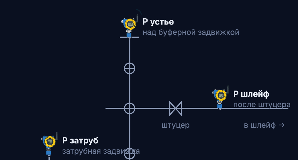
Dropping a stick into a producing well — through the wellhead launcher

The launcher is mounted on the master valve of the wellhead tree. The stick is loaded into the chamber through the loading valve; chamber pressure is equalized with well pressure through the inlet valve, taking pressure from below the discharge valve; the discharge valve opens — and the stick drops into the tubing. The well keeps producing throughout.

Animation · how the launcher works
01 · Initial position

All valves are closed — indicators red. The well is producing.The loading chamber is isolated from the well and from atmosphere.

02 · Bleeding the chamber

Open the bleed valve → excess pressure escapes through the small line. Close the bleed valve.A safety step before any work: pressure may have been left in the chamber. The loading valve can now be opened safely.

03 · Loading the stick

Open the loading valve → the stick drops into the loading chamber. Close the loading valve.The stick rests on the ball of the discharge valve; the shutters keep it from tilting.

04 · Equalizing pressure

Open the inlet valve → gas from the well (taken from below the discharge valve) fills the chamber. Close the inlet valve.Pressure on both sides of the discharge valve is now equalized — it can be opened.

05 · Drop into the well

Open the discharge valve → the stick drops into the tubing under its own weight. Close the discharge valve.The well kept producing throughout — there was no interruption.

06 · Bleed-down after the job

Open the bleed valve → pressure in the loading chamber equalizes with atmosphere. Close the bleed valve.The chamber is left depressurized — safe for the next load and for servicing.

07 · Pause

All valves are closed. The launcher is ready for the next treatment.The cycle repeats on the schedule of the treatment programme.

01 / 07
Pulse · extending field life

Chemical without feedback is working blind

The performance of a treatment cannot be judged from the fact that the chemical was dropped — it is visible only in the dynamics. Pulse makes the well observable and controllable: it collects data, shows the response of pressure and rate, manages the treatments and delivers decisions to people. Chemical selection and Pulse form one loop: the formulation is chosen for the well, while the optimal regime is found and held only on platform data.

The measure is the shape of the pressure curve itself: the recovery rate between treatments shows how fast the column builds — and therefore the required frequency; the speed and depth of the drop after a treatment show the actual unloading achieved — and therefore how well the dose and the formulation match. A slow or shallow response is visible on the curve, not by eye.

Pulse · signal path

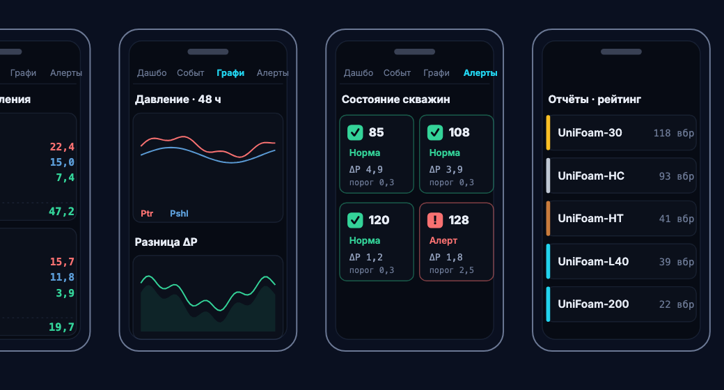
Sensors on the wells measure pressures and the operating regime of the field continuously. The signal travels over a radio link to a cloud server; field operators send events from their phones to the same place — treatments, blowdowns, voice notes — and receive feedback: confirmations, alerts, instructions. The server processes the stream continuously — formulas, algorithms, forecast — and what reaches people is not numbers but decisions: who drives out, what to treat, what to sign.

Data acquisition

Wellhead telemetry and manual entry by field staff through a Telegram bot — pressure, rate, blowdown and chemical consumption readings reach the system without dedicated workstations.

Trends and performance analysis

You can see how the pressure builds between treatments and how it falls after a treatment. From the shape of that curve the effect of each treatment is assessed and the optimal treatment point is determined — rather than judged by eye.

Treatment control

Automated launchers and dosing units deliver the chemical on a schedule or on an event (a pressure threshold being reached), in step with the well regime.

Routes and tasks

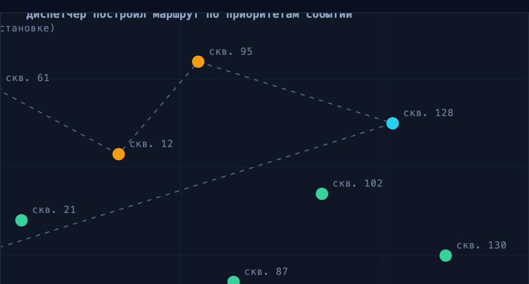
Planning field runs, assigning tasks to operators, tracking completion — the workload is distributed across the wells, not held in someone's head.

Summaries by role

Automated reports and notifications to groups by role and status: everyone receives their own slice, and deviations arrive at once.

Forecast and AI in development

Forecast of liquid accumulation and treatment timing; models for regime analysis and early detection of problems.


Well 214pad 7 · UniFoam-30
TrendsEventsTasksReports
online · 30-s polling
P wellhead
18,3kgf/cm²
▲ 1.3 after treatment
P flowline
15,5kgf/cm²
line stable
ΔP
2,9kgf/cm²
8 mm choke · above threshold
Gas rate
41,6Mm³/d
▲ 7 % week over week
Treatment regime
1per day · 2 sticks
UniFoam-30 · Operator 1
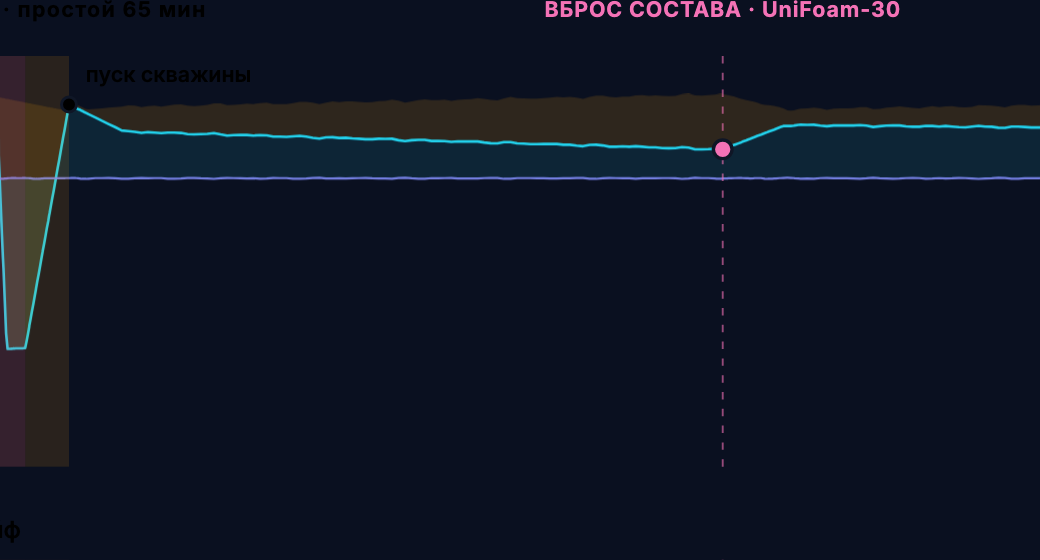
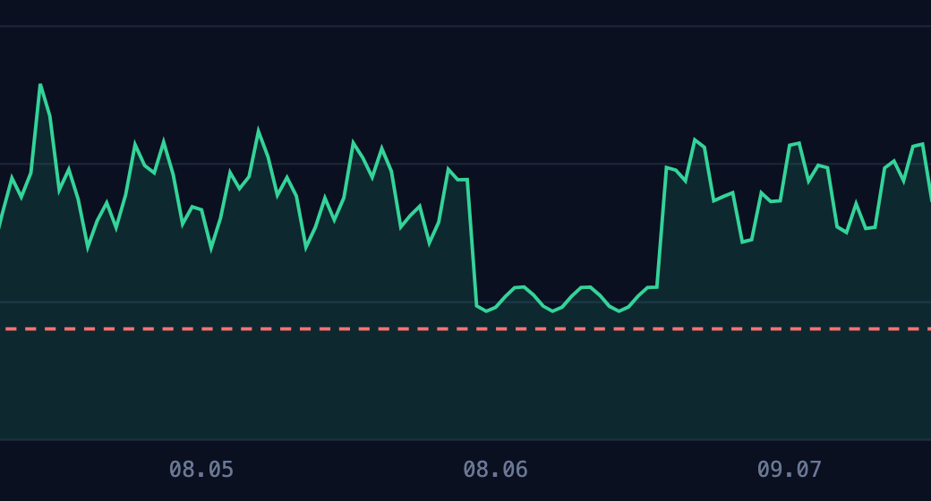
Pressure and differential · cycle: blowdown and treatmentkgf/cm² · LoRa telemetry + events · the scene repeats
P annulus P wellhead P flowline liquid columnannulus − wellhead differential across the chokewellhead − flowline treatment downtime: blowdown+ pressure build-up ΔP threshold
Event recordedthe panel runs in sync with the scene · pressures in kgf/cm²
Blowdown · 12:40 — 13:45
Opened to flare25 min
Pressure build-up40 min
Downtime65 min
Gas flared2.4 Mm³
Deferred production during downtime1.2 Mm³
P wellhead17,6 → 17,8
P annulus19,8 → 19,5
Liquid column2,2 → 1,6
ΔP across the choke2,2 → 2,4
Treatment · 14:20
FormulationUniFoam-30 · 2 sticks
Field operatorOperator 1
Downtime0 min
Gas flared0
Deferred production during downtime0
P wellhead17,0 → 18,3
P annulus19,9 → 19,2
Liquid column2,9 → 0,9
ΔP across the choke1,6 → 2,9
Blowdown per cycle
65 min downtime2.4 flared + 1.2 deferred, Mm³
Treatment per cycle
0 min downtime0 flared · 0 deferred
Cycle total
ΔP 2,4 → 2,9 65 min downtime · 3.6 Mm³
Event feed
14:20
Treatment
UniFoam-30, 2 sticks · Operator 1 · 0 min downtime
14:26
Effect recorded
ΔP 1.6 → 2.9 · column −2.1 kgf/cm²
13:45
Losses recorded
2.4 Mm³ flared + 1.2 deferred · ΔP +0.2
12:40
Blowdown
25 min to flare + 40 min build-up · 65 min downtime
07:00
Daily summary
Sent to the «Production» group
Demonstration view of the interface: it shows how the curve is read; the data is illustrative. Screens from live deployments are available on request, with anonymized data.
Services and support
01Well dataProduced water chemistry, limits and risksIonic composition, salinity, tendency to scale and corrosion. These limits govern everything that follows — outside them the formulation does not work.
02Technology selectionTesting on the water from this specific wellLiquid unloading efficiency, compatibility, emulsion stability, thermal stability — on a real sample, not on catalog figures.
03Verification at the wellThe working regime is determined at the wellField trials confirm the result and fix the treatment regime against actual pressure behaviour.
04Custom formulationWhen a standard solution does not fitWe develop or adapt a formulation for the specific conditions of the well — pressure and temperature, condensate fraction, fluid composition.
05SupportThe technology does not end at implementationFrom monitoring data the engineer adjusts the treatment frequency, the operating regime and the technology parameters.
PULSE · CONTINUOUS MONITORING

Supports the technology all the way — from the first trials to the regime in routine operation.

Focus areas

What works and where

The catalog grouped by the problem it solves. Under each one, the actual field of application.

Liquid unloading from gas wells.

Foamers convert produced water and condensate into transportable foam and carry them up with the gas stream. Separate formulations exist for water, for a water-condensate mix, for high condensate (>75 %), for high bottomhole temperature and deep wells, and for high-salinity brine.

Restarting loaded-up wells.

Gas-generating formulations create a gas cushion and agitation in a dead, watered-out well; combined with a foamer, this becomes a programme for bringing the well back from idle.

Corrosion protection.

Film-forming inhibitors against H₂S and CO₂ attack, including bacterial (SRB); separate classes cover high temperatures and injection systems.

Scale and salt bridging.

Inhibitors for carbonate and sulfate scale in the wellbore, tubing and lines; formulations that keep NaCl in solution by chelation.

Hydrogen sulfide.

H₂S scavengers acting through the water phase: neutralization and reduced toxicity of the product

Paraffin and asphaltene deposits.

Crystallization modifiers that reduce deposits in the wellbore and tubing.

Acid treatment.

Acid formulations for injection wells: removing carbonate scale and lowering injection pressure.

Drilling.

Friction reducers and dispersants for a higher rate of penetration.

Geography of use · worldwide experience

Where the formulations work

The solid chemical formulations we supply are used on gas and oil fields worldwide.

Uzbekistan Kazakhstan USA Canada Mexico Colombia Peru Chile India Libya Oman United Kingdom Nigeria Malaysia Indonesia UAE Saudi Arabia Argentina
World map — countries where the formulations are used
Sites in the region · Uzbekistan and Kazakhstan
16 countries of worldwide experience · region of presence — Uzbekistan and Kazakhstan (sites below ↓)

Sites in the region · Uzbekistan and Kazakhstan — marked on the world map above ↑

Natural Gas-Stream
Akchalak · Garbiy Barsakelmes · Chandyr · Kalandar
Karakalpakstan and Bukhara region · Uzbekistan
Uz-Kor Gas Chemical
Surgil
Ustyurt GCC, Karakalpakstan · Uzbekistan
Gazli Gas Storage
Gazli
Bukhara region · Uzbekistan
KazAzot · Shagyrly-Shomyshty
Shagyrly-Shomyshty
Mangystau region · Kazakhstan

Industrial application experience

Encana
BP
Suncor Energy
Pine Cliff Energy
Chevron
Occidental (OXY)
Anadarko
El Paso
Bonavista
Pemex
Harvest Energy
Marathon
Petronas
Devon
Canadian Natural
Shell
Pioneer Natural Resources
ConocoPhillips
Repsol
Centrica Energy
EOG Resources
Valero
Progress Energy
Focus Energy
Duke Energy
Request

Request for selection and trials

Describe the well parameters and we will select a formulation, calculate an approximate dosage and propose a field trial programme. Supplied as an authorized distributor; manufactured in Texas, USA.

+998 93-920-92-22Uzbekistan · phone +7 771 838 11 10WhatsApp · phone +380 97 953 93 32Telegram · WhatsApp · phone info@unitool.uzrequests and technical consultation
TashkentYunusabad district, 21B Bogishamol St.
KungradRep. of Karakalpakstan, Kungrad district, Azatliq MFY, G'a'rezsizlik ko'chasi, 11

Well parameters